Reproducing Cadmium Sulfide Light Dependent Resistor Transistors
August 2023
I've been dreaming of building transistors and integrated circuits at home since a long time. A while ago, I found Nyle Steiner's article about using an LDR (light dependant resistor) as an improvised field effect transistor(FET). Since I had all components to try and reproduce this experiment at home, I set the circuit up and took some measurements.
Test Circuit
The LDRs I used have a resistance between 5 kΩ and 10 kΩ and are made out of cadmium sulfide like Nyle Steiner's. To prevent shorts, I used another 2.2 kΩ resistor in series with the LDR. A circuit diagram can be seen below.
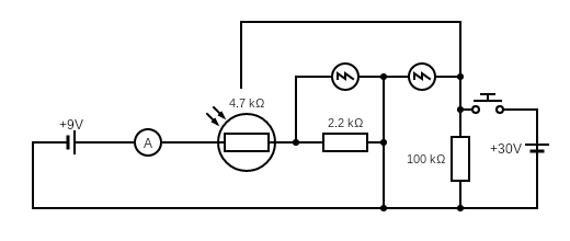
Depending on the exact measurement, the polarity of the 30V power supply was reversed. Additionally, I couldn't go above 30V, because that's the max my power supply can deliver. I can imagine that you will need a higher voltage to get better results. Neil Steiner talks about upt to 175V in his experiments, although it is unclear what lead to the best results. Maybe I'll build a voltage booster in the future, as the currents that flow aren't very high.
Results
Obviously the experiments were carried out in complete darkness to avoid influences of light. That's also why you only see the screen of the oscilloscope on the images.
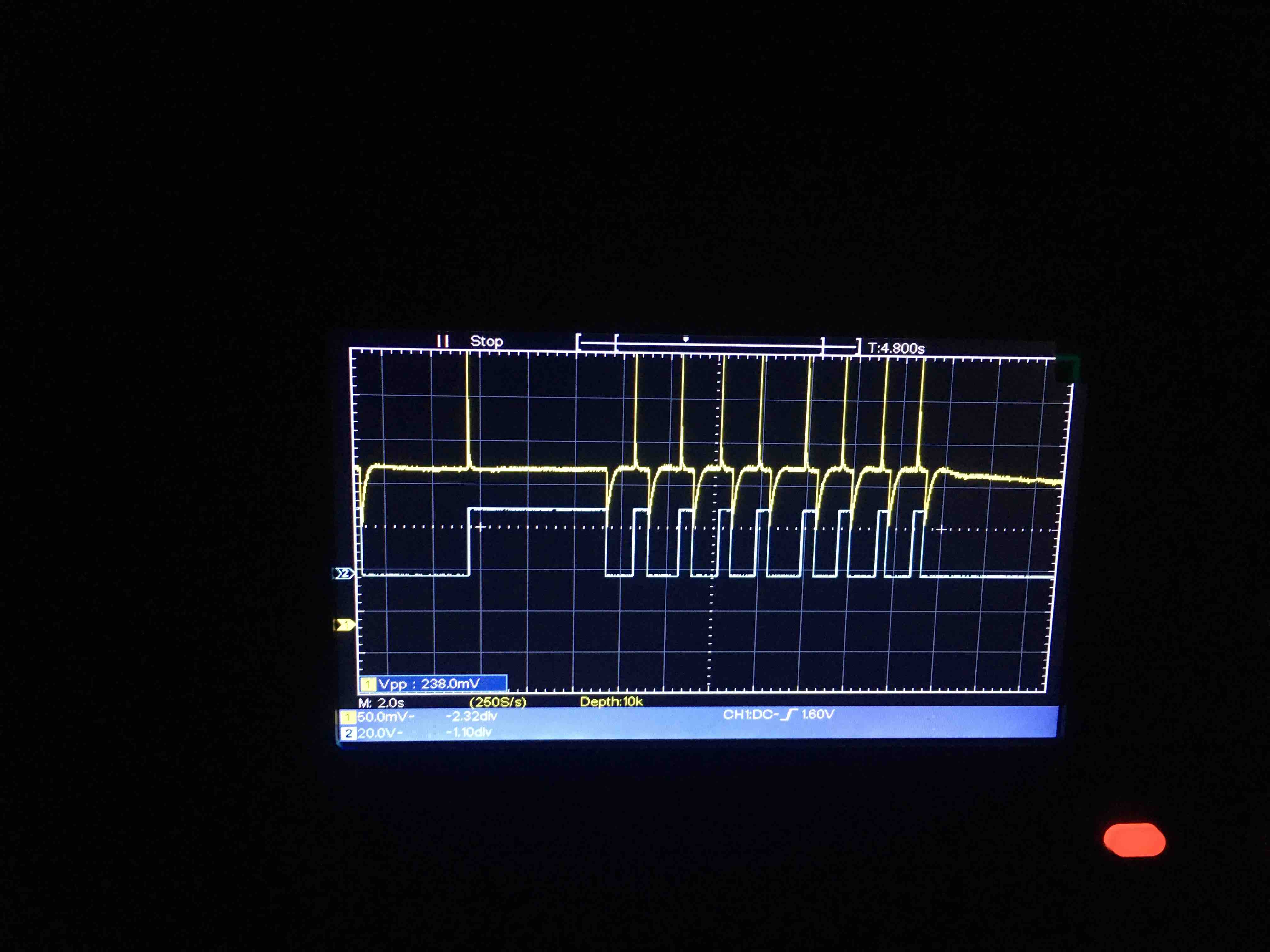
Using a positive gate voltage (blue line) triggers a small response on the edges. The power supply voltage is +30V and the battery around 8V.
Using a positive gate voltage (blue line) triggers a small response on the edges. The power supply voltage is +30V and the battery around 8V.
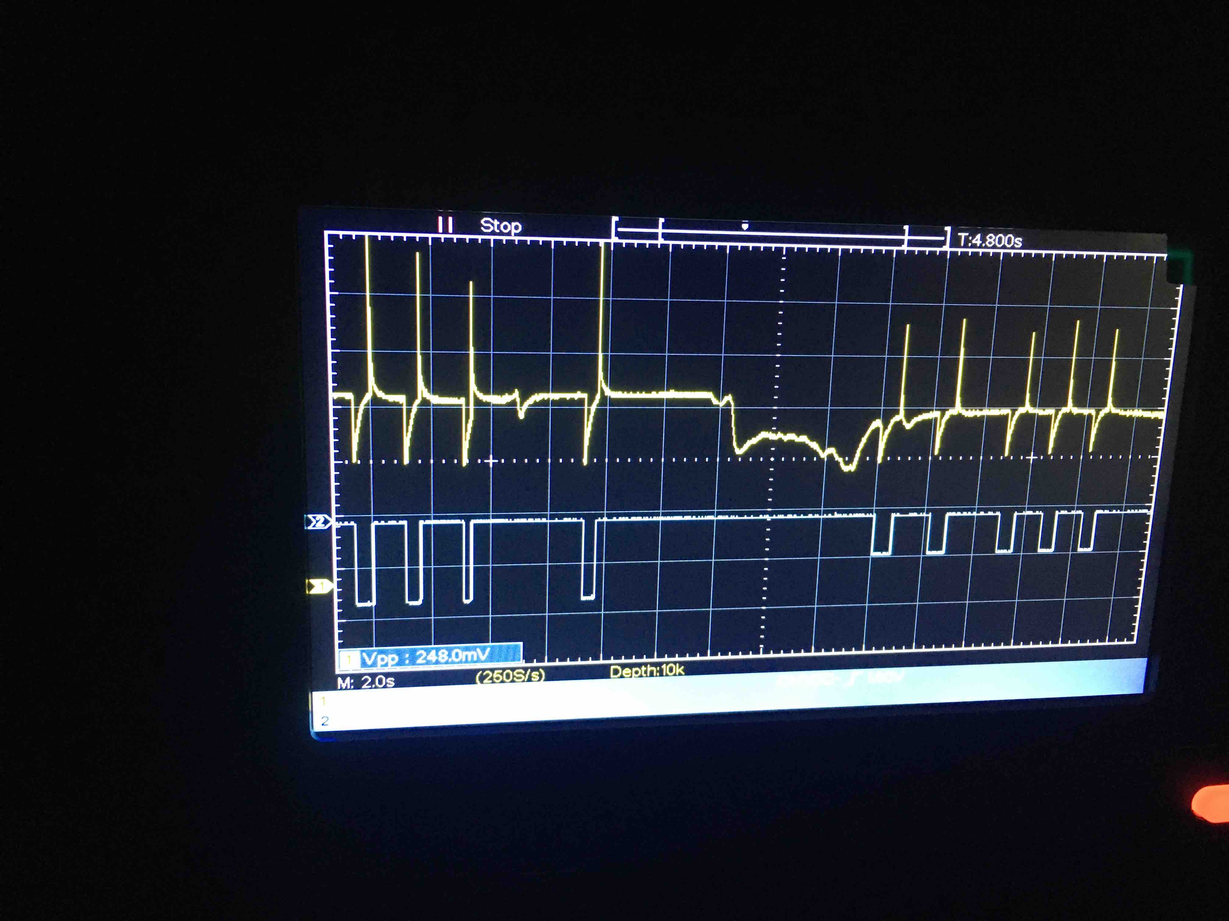
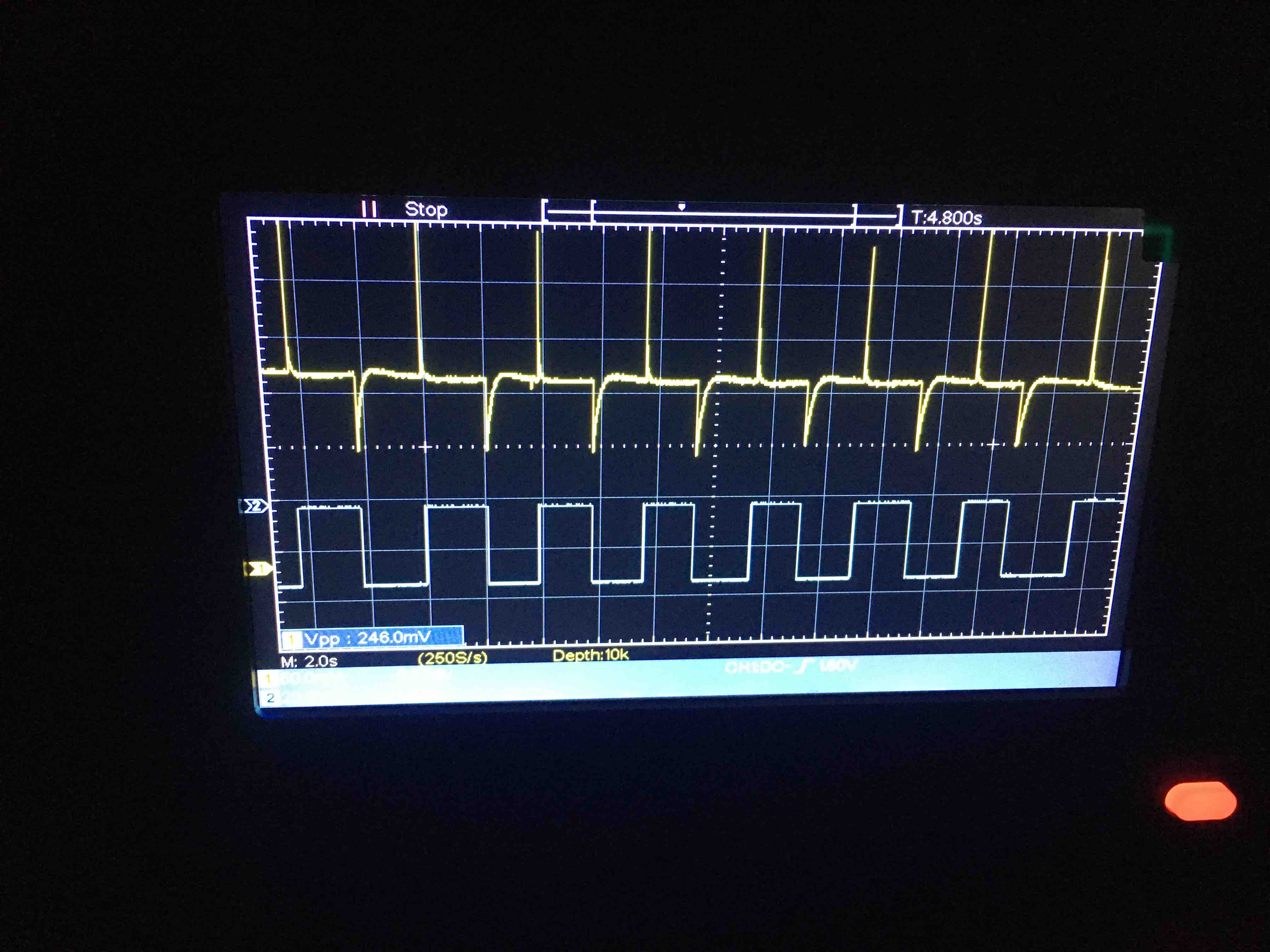
Using a negative gate voltage (blue line) triggers a small response on the edges. The battery voltage is around 8V. The power supply(gate) voltage has been changed from 30V(left side) down to 15V(right side). It can be seen that a lower voltage leads to a smaller response on the edges.
Without the water, no effect can be observed.
Discussion
Looking at the data, it isn't clear whether it is a FET that we are observing. There are only changes on the edges, not while holding a voltage level. These spikes immediately fall back to the normal level. I could imagine that this is capacitance or inductance, but I don't know electronics well enough to confirm or deny it. It is weird that the effect isn't the same for positive and negative edges though. On the other hand, Nyle Steiner mentions that he observes a similar effect:
The response of this device also seemed to have a dynamic characteristic. That is, whenever the reversing switch was activated, the current through R2 would suddenly change and then slowly creep back toward the previous value. By running a sawtooth waveform into the gate however, I was able to establish to my satisfaction, that indeed the output current was responding to the input voltage.
However, his article doesn't provide enough data to see if this is the same effect. Since I don't have a wave generator available, I can't check if it works better with waveforms, like Nyle Steiner did it.
Conclusion
While an effect can be observed when the gate voltage changes, it is unclear to me if it is caused by a FET effect. Perhaps the higher voltage Neil used in his experiments makes a difference, but I can't test it since I don't have access to a power supply providing more than 30V.
EDIT: Looking at the graphs again with a better understanding of electronics, they look exactly like capacitors charging and discharging. A MOSFET or this improvised LDR-FET do also act as capacitors since they contain two conductors (the LDR's resistance is still close to a conductor) separated by an isolator